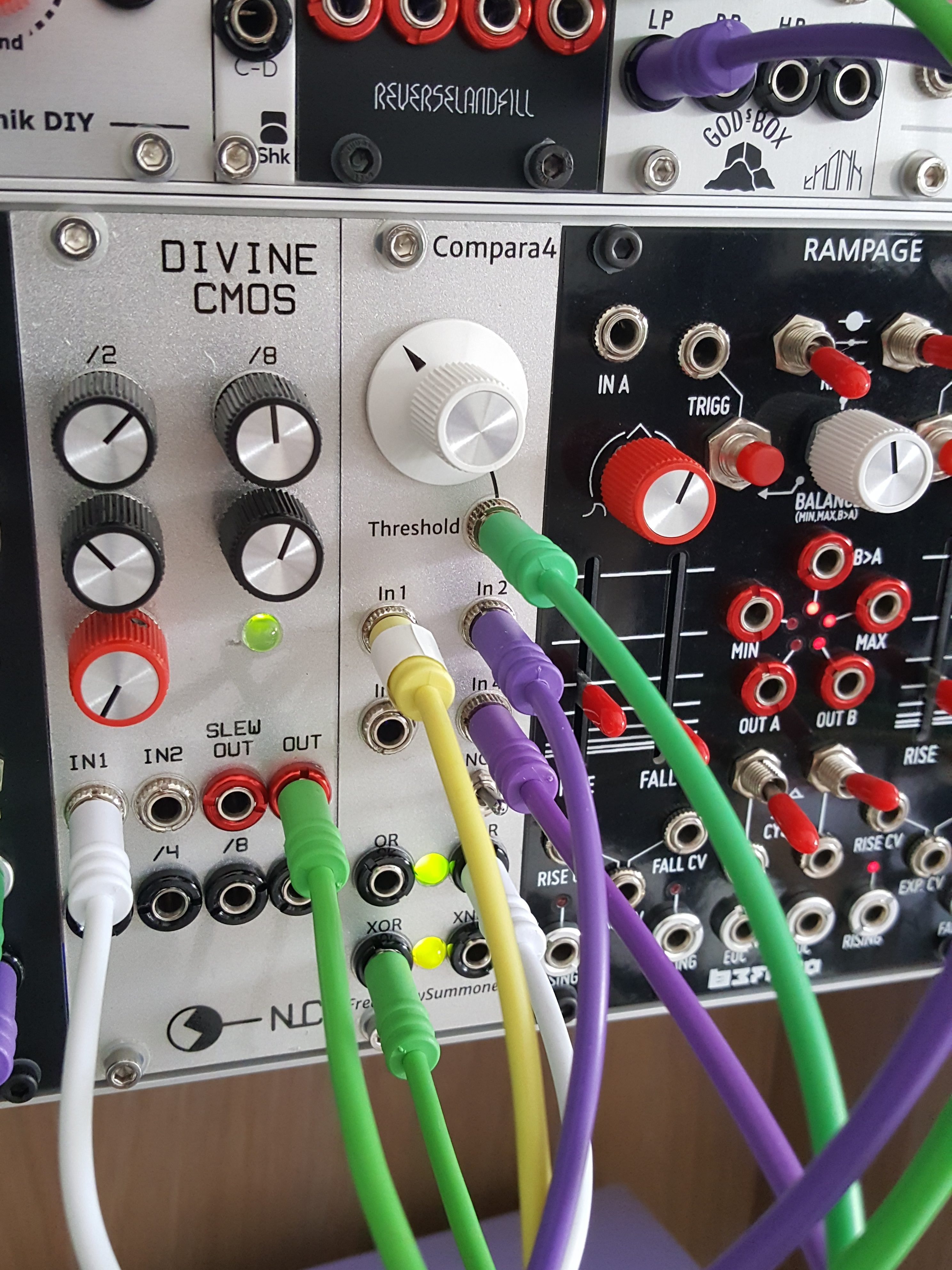
I made another original module for my synthesizer! It’s called Compara4 and it’s a quad comparator / logic in 6hp for the Eurorack format. So far only one exists, I built it on prototyping board. I’ll outline some of the design ideas and lessons learned; maybe someone else would like to build one!
There aren’t any audio/video demos yet, need to figure out a workflow for that…
Concept
While Llama Llama Duck is designed as several simple independent sections chained together, Compara4 is the opposite: a more tangled set of functions which can reduce to simpler purposes by leaving some inputs/outputs unused. So this fairly compact module can be a comparator, a gate-combiner, an inverter… or an interesting combination of the above, which will turn multiple modulation inputs into streams of gates.

The OR output is high when any input is positive, while XOR is high when an odd number of inputs are positive. Complementary NOR/XNOR outputs are provided, and for an additional variation the fourth comparator output can be inverted.
The concept was partly inspired by my need for a gate combiner; I also didn’t have a comparator, which seems a useful building-block in general. Further encouragement came from the realisation that comparators are basically “free”: most Eurorack inputs use some kind of op-amp buffer to set the input impedance and avoid unexpected interactions between modules. The input buffer can be converted to comparator simply by moving resistors around; a cheap TL074 chip provides four comparators. Modular synth electronics should be voltage-controllable where possible to allow automatic modulation. Some circuits (e.g. filters) are tricky to modify for voltage control, replacing resistors with inconsistent optical elements or redesigning to allow current-control with an OTA (probably at lower signal voltages). But comparators are easy; the threshold is set by high-impedance voltage input.
Implementation
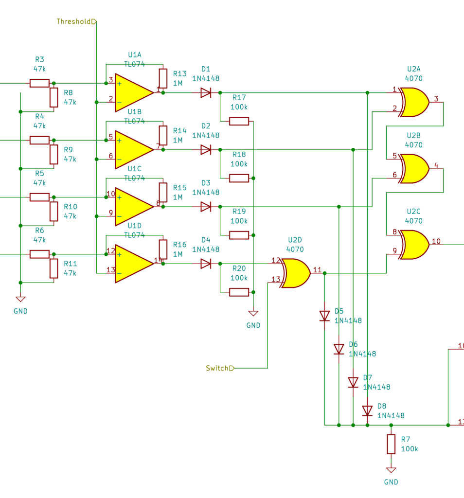
The schematics were drawn up with KiCad and are available on Github. Here’s a PDF version. It’s really quite similar to the block diagram, but a few implementation details are worth discussing.
The TL074 comparator section runs on +/- 12V. A quirk of the TL07x series means that this still isn’t quite able to handle the full range of possible input voltage; these ICs handle extreme negative voltages poorly, so 47k resistor pairs act to a) set a ~100K input impedance b) halve the voltages. The threshold is also divided this way (on the other sheet) so the comparison is consistent, but a bit of error will be accumulated from component tolerances.
The following CMOS logic chips run on 0-12V, so a set of diodes and pulldown resistors limit the comparator output voltages to a safe range. The OR logic is then achieved by a set of parallel diodes; if any channel is high, this voltage will pass the diodes without contaminating other “low” channels. The 4-way XOR is achieved with a CD4070 chip, which is a quad 2-way-XOR package. Three of these are cascaded to give a 4-input XOR; the remaining XOR is used to implement a switchable NOT for the fourth channel. (Logic is pretty neat, apparently you can build anything with enough NAND gates. Should try that some time…)
Finally, another CMOS chip is used for the outputs: a CD4041 “quad complementary logic buffer”. Each section takes one input, and outputs one “high” and one “low”, which switch places depending on the input state. As well as deriving our NOR/XNOR outputs, these make quite elegant bipolar LED drivers. This is illustrated with a pair of LEDs, but Compara4 uses a single bipolar LED package which encapsulates such a pair in one bulb. I had a useful discussion with some Modwiggler users about the safety of exposing the CMOS outputs to Eurorack without another buffer stage; we concluded that it’s probably ok, but… uh… use at your own risk. Protection with diodes/transistors is possible but adds complexity and may be unnecessary. It was also suggested that maybe circuits like this one could operate at mostly 5V for energy efficiency. Something to play with in future?
Layout and finishing
A lesson learned from Llama Llama Duck was to try planning the layout for designs of similar or greater complexity. Also, while I enjoyed using the Sourcery board I wanted to allow a bit more space and get some experience with traditional hole-per-pad “perfboard”. This helpful article shows how the KiCad PCB design features can be used to figure out a stripboard layout; just stick to the appropriate grid, use wide tracks and keep to some rules about spacing and directions of connections. I adapted the idea to develop a perfboard layout; non-vertical jumpers on the upper side and non-horizontal connections on the lower side are now permitted, but straight lines are still preferred where possible to avoid clutter and make good use of component-lead connections. Even so, the resulting layout is a bit intimidating and I’m very glad it was done with CAD; KiCad indicates which parts should be connected and can run an error report from the schematic, pointing out missing or inappropriate connections. Still, having done this once for perfboard I’m feeling less sceptical about using stripboard for a future project; you can get a lot done with jumpers and it would cut down on fiddly soldering.
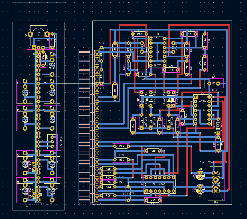
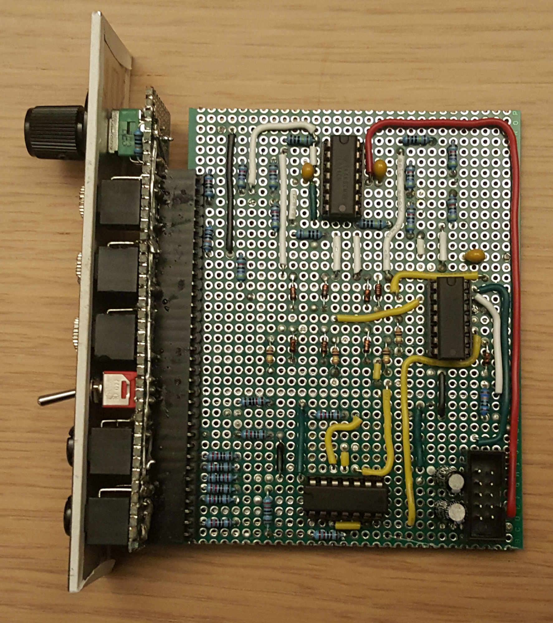
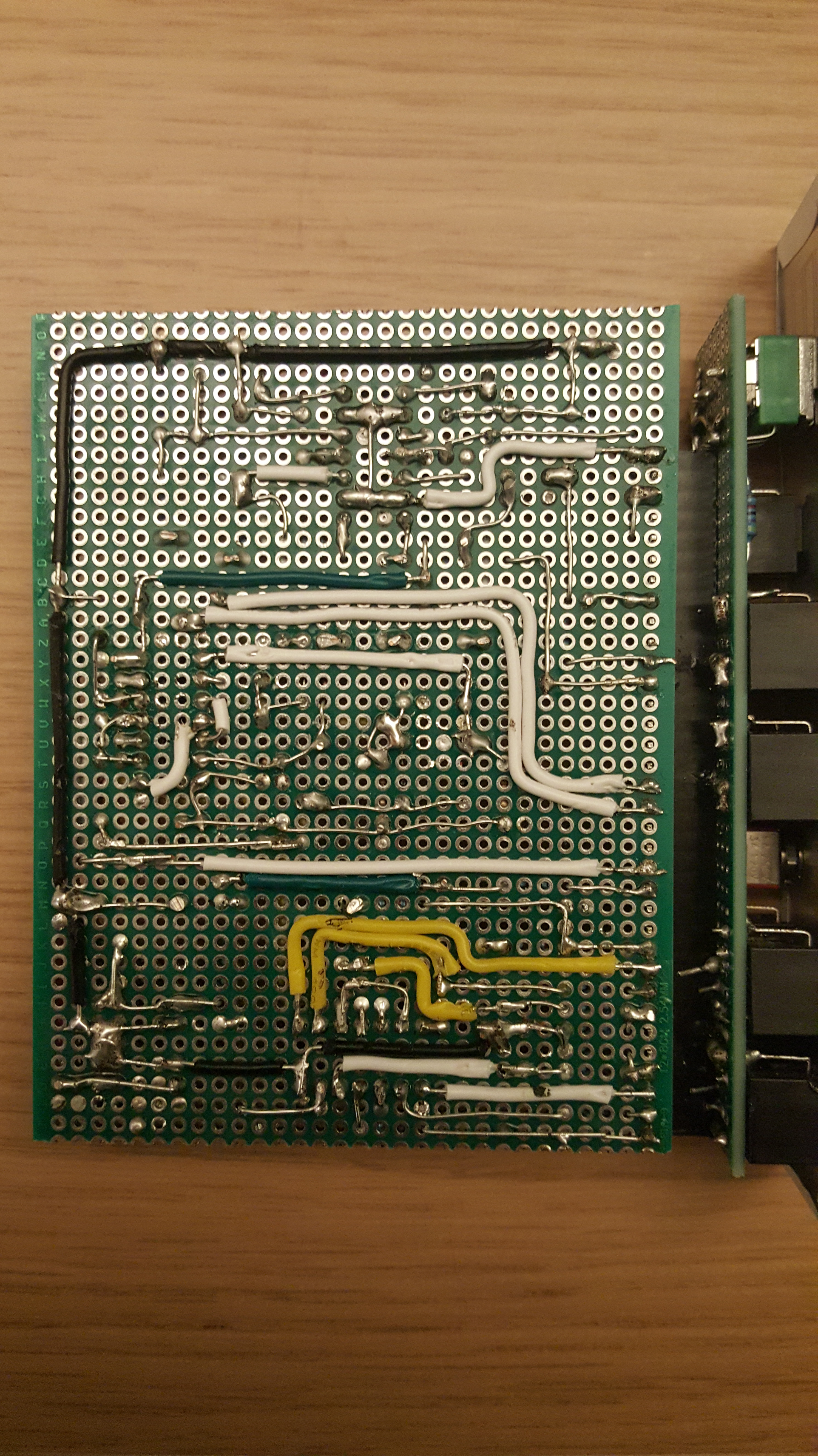
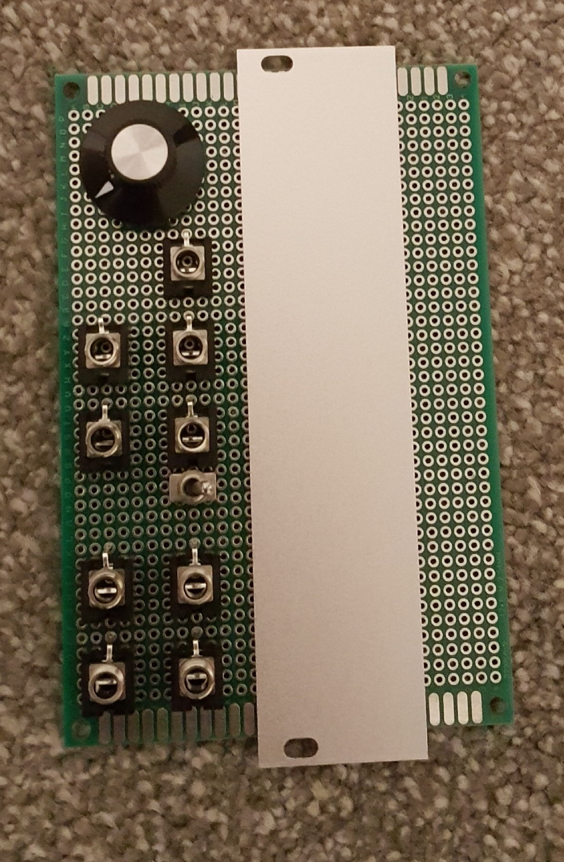
Mostly things get crowded around the three chips, which is understandable as each has four sections, taking inputs from a common direction and sending outputs in a common direction. Typical pin layouts do not facilitate this, so a bit of crossing-over is inevitable! But in KiCad this became quite a satisfying jigsaw puzzle; I can see how PCB design becomes a long refinement process.
The front panel was worked out on paper and refined by plugging components into perfboard, before making a drilling template and transparency graphics in Inkscape. The end result looks pretty professional, but there is supposed to be a shaded rectangle grouping In 4 with the NOT switch and this is very faint. On Llama Llama Duck the shading was a touch dark. More experimentation needed!
Conclusions
I’m really happy with the form factor: 6hp with a big knob and LEDs tucked between two columns of jacks. It’s comfortable to use without much wasted space. It does the intended job as a modulation/logic processor but in practice is also a lot of fun at audio-rate, creating variable-width pulse outputs from sources other than oscillators. (Detuned groups of oscillators make good drones!)

