
I started designing my own modular synthesiser components. I wrote a few words here about how that fits into my life. This is my first original module design.
Well, I say original, but let’s give credit where it’s due: this is mostly based on stuff I’ve learned by looking at schematics from Nonlinearcircuits and Mutable Instruments, blog posts by Northern Lights Modular and hanging out on the Modwiggler forum. This particular design is also heavily influenced by some classic guitar pedals.
Overview
Here is a block diagram of the module. This makes it clear that there are essentially three independent functions, but default “normalled” connections link them together to provide a combined function. This structure is inspired by “Serge” design conventions, in which complementary units are brought together in a single panel, dividing up a regular grid layout of controls and jacks. However while Serge systems use “banana” jacks (which have the advantage of easily stacking to split one output to many inputs), Eurorack uses smaller and more complex 3.5mm jacks which include a “switching” feature to pass a default signal when disconnected.

Distortion
So, what’s the deal with the AC/DC clipping stages? Well, I like the idea of the Tube Sound Fuzz, Red Llama and similar guitar distortion circuits, which abuse a CMOS logic chip to create a “tube-like” (soft and asymmetric) distorted gain stage. But guitar pedals have to make a few design compromises; although the input/output signal range is bipolar around 0V, they use a “single-sided” power supply between 0 and 9V (to support the use of convenient batteries). The processing needs to happen about some non-zero reference voltage, with a “bias” shift at the input and output. There’s an easy way of doing this: “AC-couple” the circuit with series capacitors. In the process we filter out the lowest frequencies; a non-issue for electric guitar. In a modular synthesizer this is sometimes a useful side-effect, getting a bit of headroom for unipolar input signals and avoiding excessively asymmetric clipping. The first section of Llama Llama Duck follows this scheme. The manual gain control can be used to dial things back into a kind of AC-coupled buffer, or push into pleasant distortion.

Each inverter stage acts as an inverting amplifier when setup in this negative-feedback configuration. The principle is the same as an inverting opamp, making use of a linear region in the middle of the voltage range. There is heavy soft-clipping on one side of the transfer curve; to get something remotely symmetric we use two stages. The chip has six inverters on it, so we may as well use some more…
The joy of modular, for me, comes in the presence of generic processes that make sense for both control-voltage (CV) and audio signals. It should be possible to use distortion to reshape CV, and manipulate audio distortion by injecting interesting modulation sources. The above AC-coupling approach blocks DC and prevents such shenanigans. But the CD4049 can’t handle the full +/-12V Eurorack power supply; either it has to run “single-sided” or we need to regulate e.g. +/-6V rails within the module. I took the approach of dialling in bias voltages with a trimpot. Original experiments used two trimpots, but it turns out that one will do; as long as the output lines up properly (i.e. return 0V for 0V input) it doesn’t matter if the 4049 inputs are slightly off-centre.

A couple of other details are worth mentioning: a secondary input and clipping diode. Adding DC bias creates all sorts of nice fuzz effects, so an extra input is provided with a level potentiometer. (This works nicely with Section 3, as we shall see.) The diode is a precaution to prevent the U2C input node from being exposed to negative voltages if an unusually low input voltage is supplied. The inverting configuration keeps the node at ~6V but would need a lot of current in such a case. This shows up as a bit of hard-clipping in the output but isn’t really noticeable for sensible inputs.
The gain levels are fixed but fairly useful; a bit over +6dB of gain, and peak levels clipped to around +/-5.5V. This plays well with typical Eurorack oscillator signals which are 10V peak-to-peak. For more gain, consider pre-processing with section 1. For less gain, use the attenuating input.
Release envelope
Section 3 is a simple envelope generator with a fast attack stage, fixed sustain and variable release speed. I came up with it messing around on solderless breadboard but I doubt there’s anything unusual or clever going on: it’s just a comparator and slew limiter.
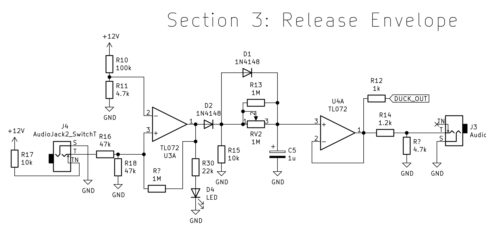
An LED indicator is driven by the comparator rather than the output; not really clear if that was a good idea. The timing control uses a 1M linear pot in parallel with a 1M resistor to approximate a 500k logarithmic taper.
Why include a release envelope on a distortion unit, anyway? Well, it’s “normalled” to the DC In 2. If you send a clock to it, this will “fuzz” the audio running through that section’s other input by smashing the signal into one side of the clipping so hard it gets quieter. The result is something a bit like the classic dance music pumping / ducking effect. But weirder and noiser! That’s why this is the “duck” section. And when I realised that would mean the module could be named Llama Llama Duck, well…
Construction
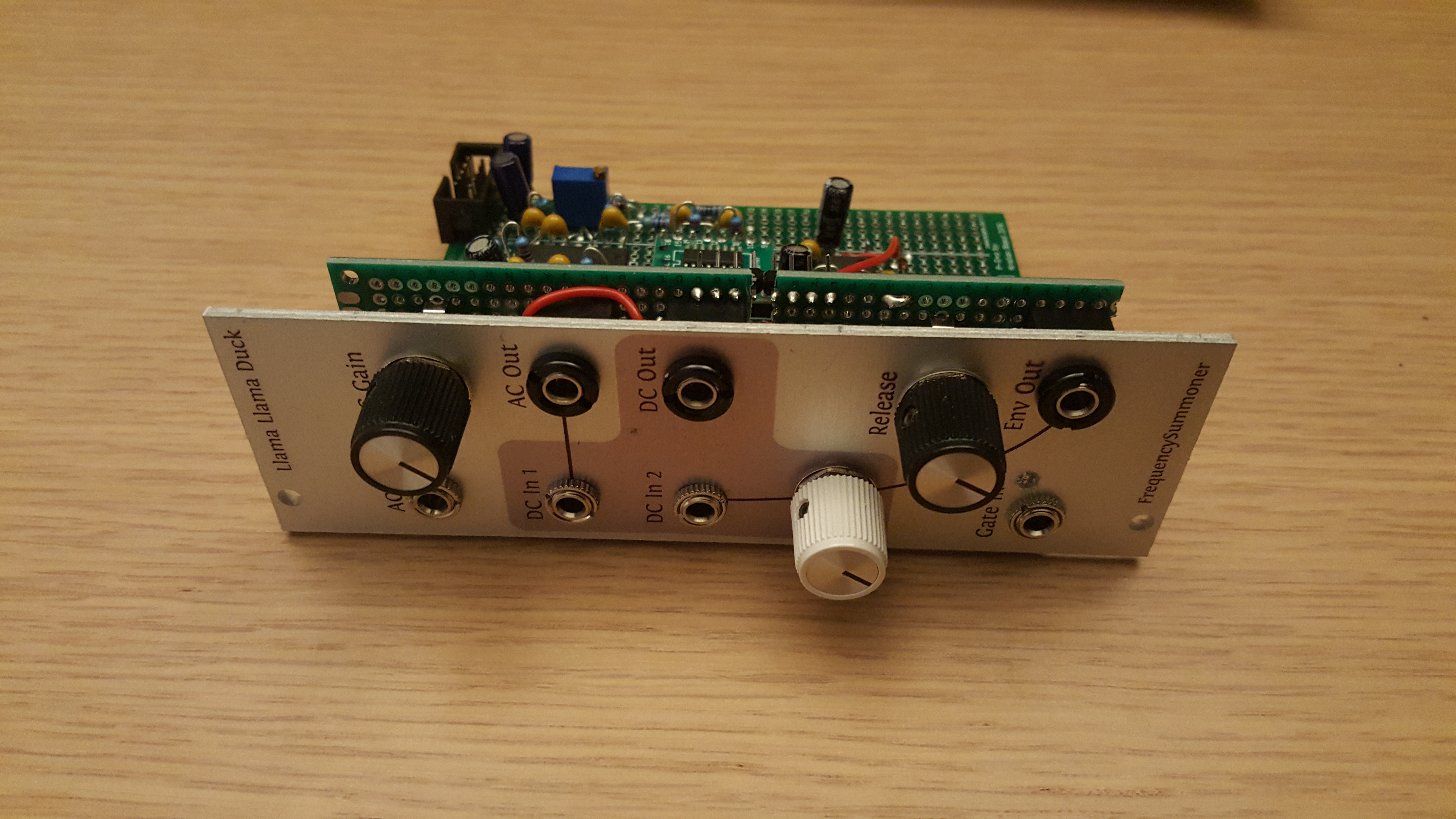
After testing with solderless breadboards the circuit was built “freestyle” from the schematic on a Sourcery protoboard. The board was really nice to work with, having a neat power-bus system that allows IC power to be routed by soldering across a few pads. The control board was done with a few bits of regular perfboard, soldering wires and tracks to a header strip. In hindsight this would have gone more easily with a bit more planning; there was a lot of checking back-and-forth between the header strips, and mistakes were awkward to fix where leads crossed over.

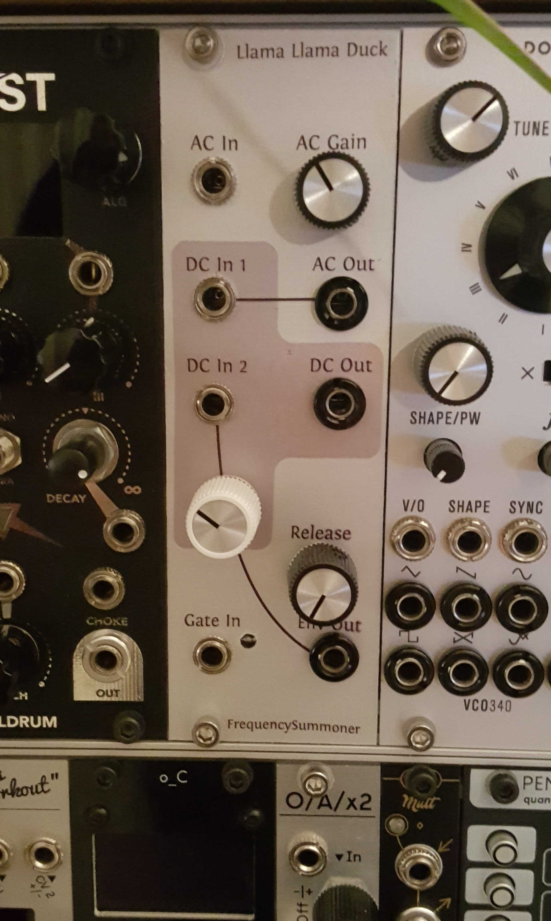
The front panel was created as an inkjet waterslide on a drilled Doepfer blank panel. The drilling template and graphics were done with Inkscape. The knob/jack choices partly follow existing conventions in my modular system; I use chunky Bananuts to indicate outputs and knurled nuts for inputs. White knobs are attenuators, black knobs are offsets or direct controls. The waterslide colours ran slightly, turning grey into pink. I don’t really mind, but will try to refine that process a bit… I really like the on-grid section divisions of Serge-style panels and the consistent, informative design of Intellijel panels. I expect my approach will evolve, but for now the principles are: indicate independent sections; indicate normalisation; keep it playable. The ergonomics of knob/jack access are easily overlooked and many modules feel over-crowded.
Apologies if this post made absolutely no sense, it’s more of a DIY build log really. Hopefully there are more to come 😀

One thought on “Eurorack module design: LlamaLlamaDuck, a CD4049-based distortion envelope thing”