Eurorack module design: Compara4

I made another original module for my synthesizer! It’s called Compara4 and it’s a quad comparator / logic in 6hp for the Eurorack format. So far only one exists, I built it on prototyping board. I’ll outline some of the design ideas and lessons learned; maybe someone else would like to build one!

There aren’t any audio/video demos yet, need to figure out a workflow for that…

Compara4 synthesizer module standing upright. An aluminium panel is labelled with 9 input/output jacks, a switch and a large control knob. A circuit board is seen extending behind the panel, with colourful wires and black chips

Concept

While Llama Llama Duck is designed as several simple independent sections chained together, Compara4 is the opposite: a more tangled set of functions which can reduce to simpler purposes by leaving some inputs/outputs unused. So this fairly compact module can be a comparator, a gate-combiner, an inverter… or an interesting combination of the above, which will turn multiple modulation inputs into streams of gates.

Block diagram: four inputs are compared with a common threshold before processing to provide four different logic outputs.

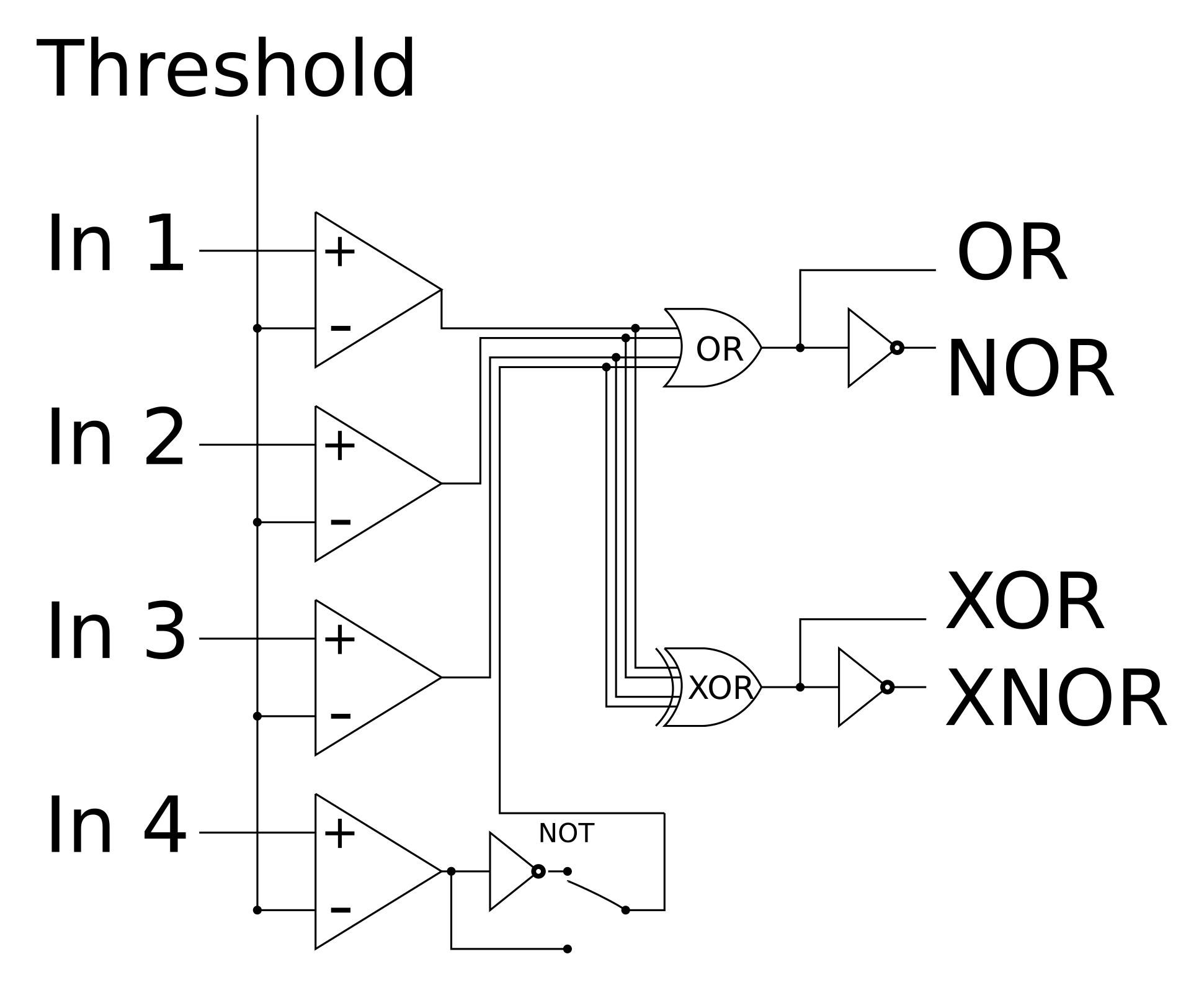
The OR output is high when any input is positive, while XOR is high when an odd number of inputs are positive. Complementary NOR/XNOR outputs are provided, and for an additional variation the fourth comparator output can be inverted.

The concept was partly inspired by my need for a gate combiner; I also didn’t have a comparator, which seems a useful building-block in general. Further encouragement came from the realisation that comparators are basically “free”: most Eurorack inputs use some kind of op-amp buffer to set the input impedance and avoid unexpected interactions between modules. The input buffer can be converted to comparator simply by moving resistors around; a cheap TL074 chip provides four comparators. Modular synth electronics should be voltage-controllable where possible to allow automatic modulation. Some circuits (e.g. filters) are tricky to modify for voltage control, replacing resistors with inconsistent optical elements or redesigning to allow current-control with an OTA (probably at lower signal voltages). But comparators are easy; the threshold is set by high-impedance voltage input.

Implementation

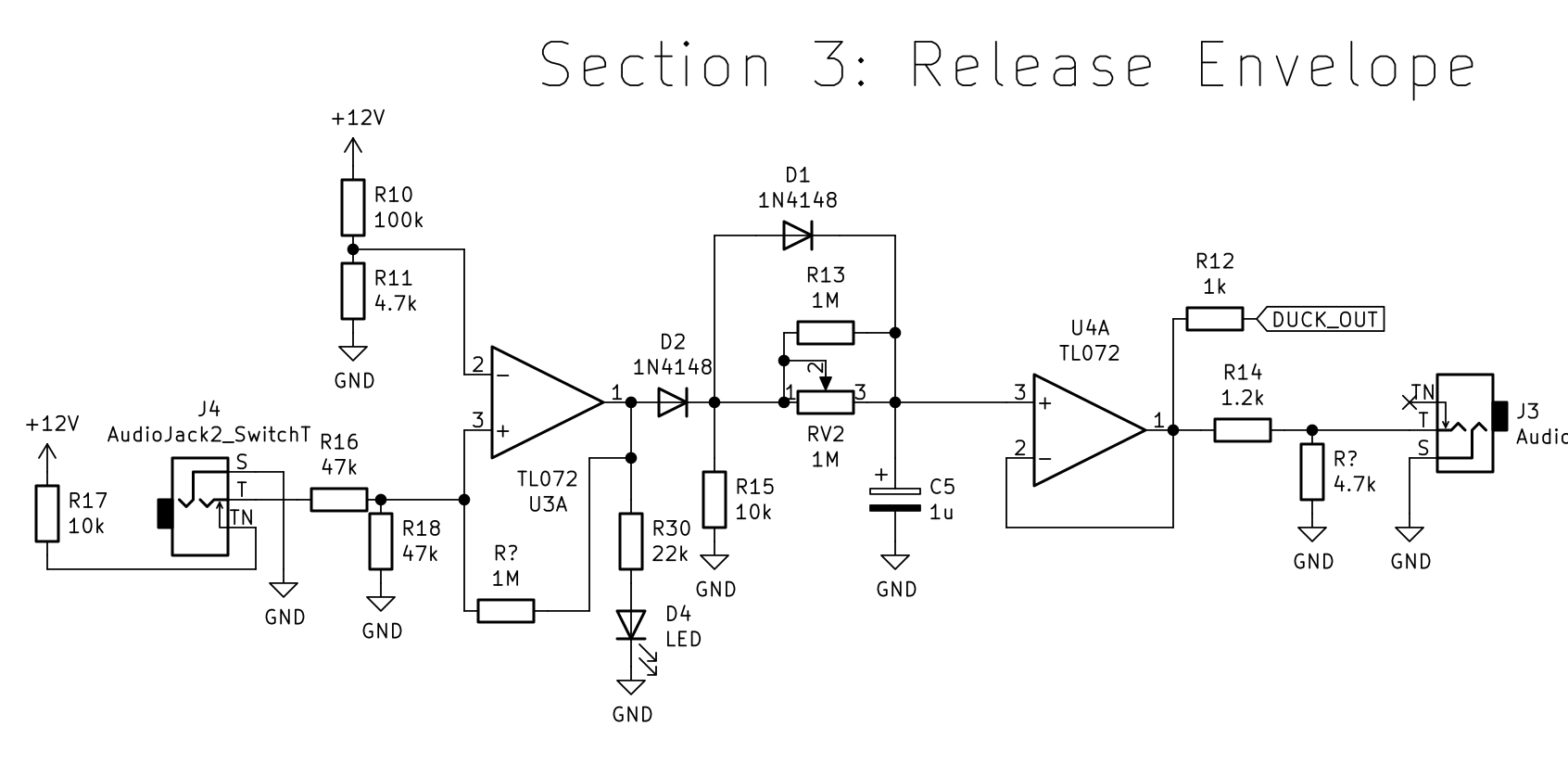
The schematics were drawn up with KiCad and are available on Github. Here’s a PDF version. It’s really quite similar to the block diagram, but a few implementation details are worth discussing.

Extract from electronic schematic. Lots of resistors, diodes, op-amps and XOR logic.
Compara4 schematic extract, showing comparators, NOT, OR and XOR sections.

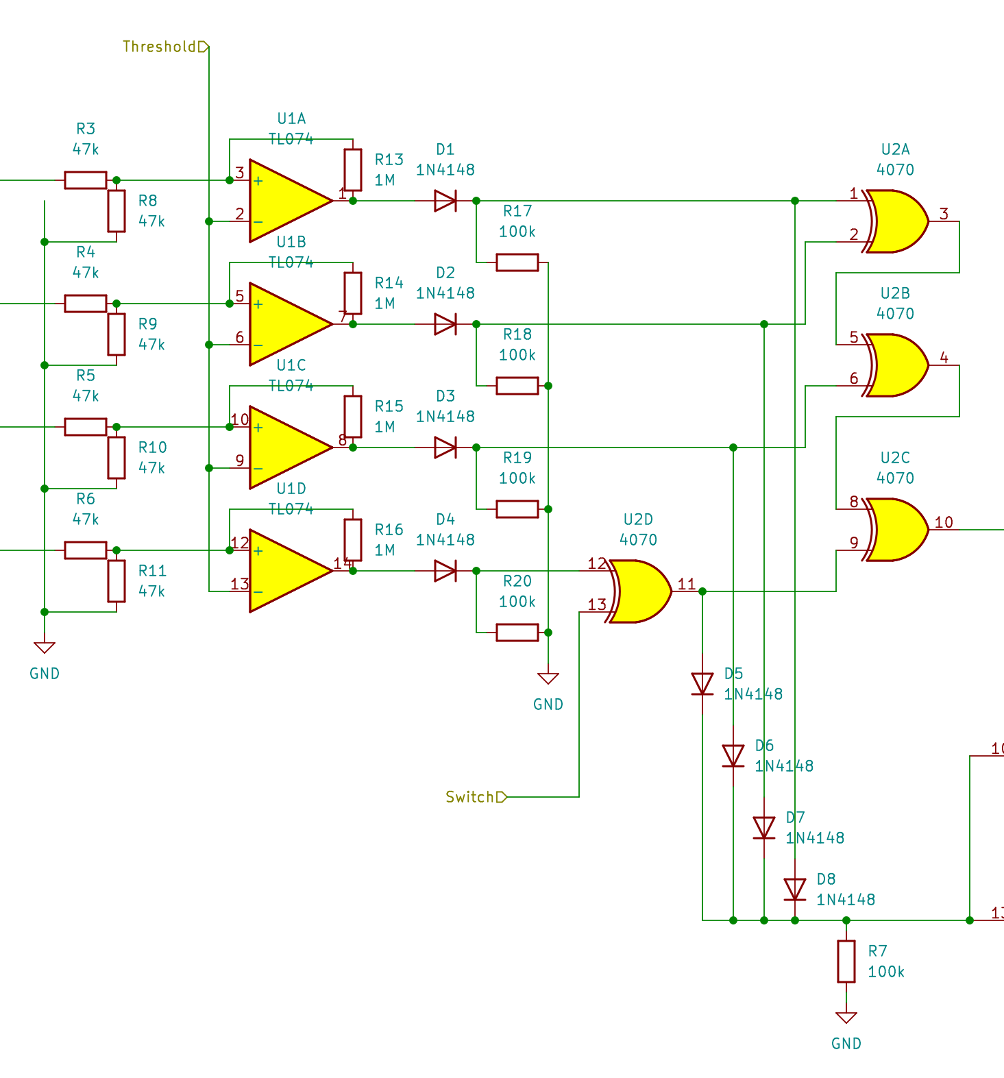
The TL074 comparator section runs on +/- 12V. A quirk of the TL07x series means that this still isn’t quite able to handle the full range of possible input voltage; these ICs handle extreme negative voltages poorly, so 47k resistor pairs act to a) set a ~100K input impedance b) halve the voltages. The threshold is also divided this way (on the other sheet) so the comparison is consistent, but a bit of error will be accumulated from component tolerances.

The following CMOS logic chips run on 0-12V, so a set of diodes and pulldown resistors limit the comparator output voltages to a safe range. The OR logic is then achieved by a set of parallel diodes; if any channel is high, this voltage will pass the diodes without contaminating other “low” channels. The 4-way XOR is achieved with a CD4070 chip, which is a quad 2-way-XOR package. Three of these are cascaded to give a 4-input XOR; the remaining XOR is used to implement a switchable NOT for the fourth channel. (Logic is pretty neat, apparently you can build anything with enough NAND gates. Should try that some time…)

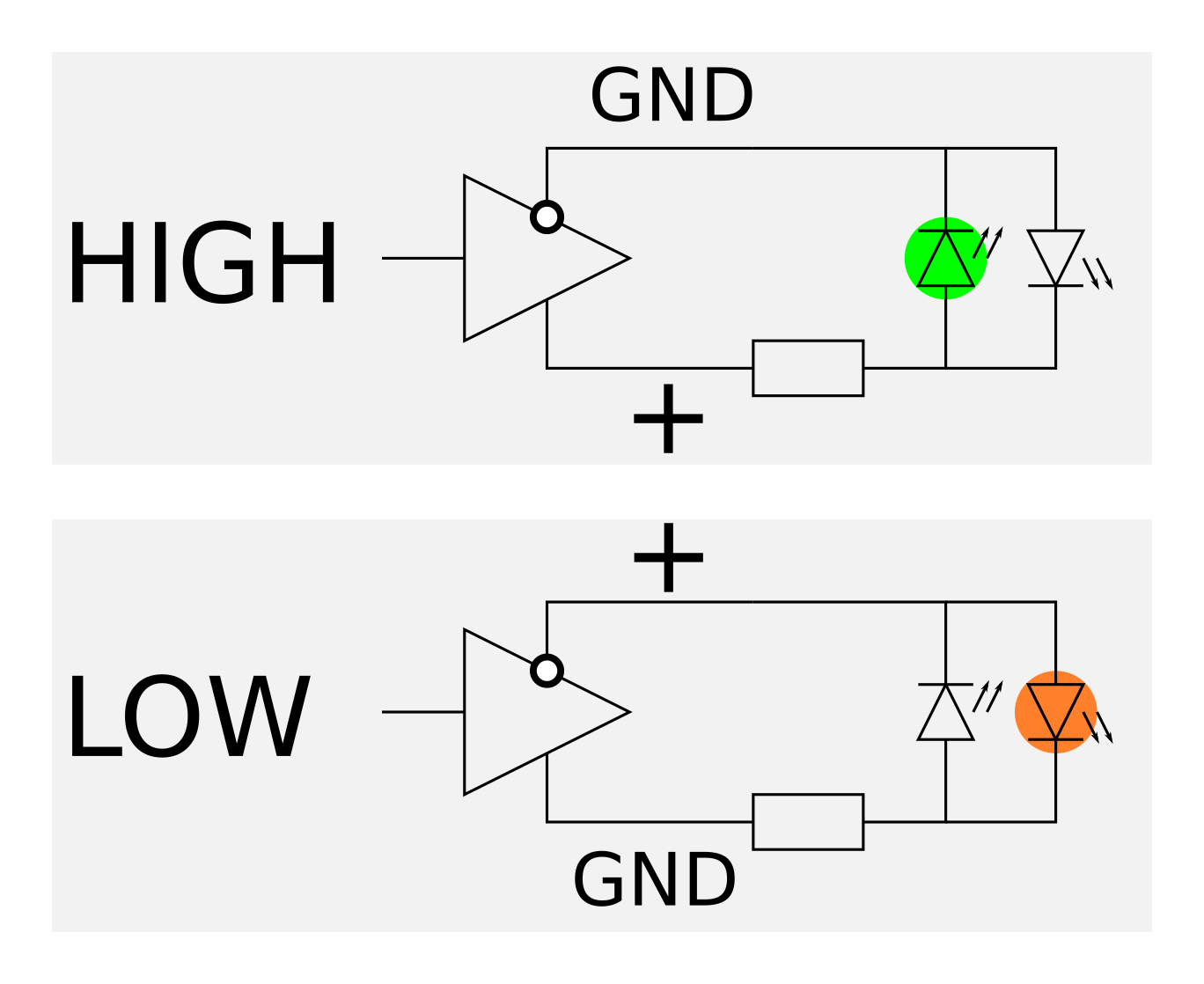
Finally, another CMOS chip is used for the outputs: a CD4041 “quad complementary logic buffer”. Each section takes one input, and outputs one “high” and one “low”, which switch places depending on the input state. As well as deriving our NOR/XNOR outputs, these make quite elegant bipolar LED drivers. This is illustrated with a pair of LEDs, but Compara4 uses a single bipolar LED package which encapsulates such a pair in one bulb. I had a useful discussion with some Modwiggler users about the safety of exposing the CMOS outputs to Eurorack without another buffer stage; we concluded that it’s probably ok, but… uh… use at your own risk. Protection with diodes/transistors is possible but adds complexity and may be unnecessary. It was also suggested that maybe circuits like this one could operate at mostly 5V for energy efficiency. Something to play with in future?

Complementary buffers as bipolar LED drivers

Layout and finishing

A lesson learned from Llama Llama Duck was to try planning the layout for designs of similar or greater complexity. Also, while I enjoyed using the Sourcery board I wanted to allow a bit more space and get some experience with traditional hole-per-pad “perfboard”. This helpful article shows how the KiCad PCB design features can be used to figure out a stripboard layout; just stick to the appropriate grid, use wide tracks and keep to some rules about spacing and directions of connections. I adapted the idea to develop a perfboard layout; non-vertical jumpers on the upper side and non-horizontal connections on the lower side are now permitted, but straight lines are still preferred where possible to avoid clutter and make good use of component-lead connections. Even so, the resulting layout is a bit intimidating and I’m very glad it was done with CAD; KiCad indicates which parts should be connected and can run an error report from the schematic, pointing out missing or inappropriate connections. Still, having done this once for perfboard I’m feeling less sceptical about using stripboard for a future project; you can get a lot done with jumpers and it would cut down on fiddly soldering.

Wiring layout with KiCad 6. Both panel and main board are drawn in the same document, for ease of understanding and lining things up. Blue lines indicate copper-side wiring, red lines are jumpers on component-side.

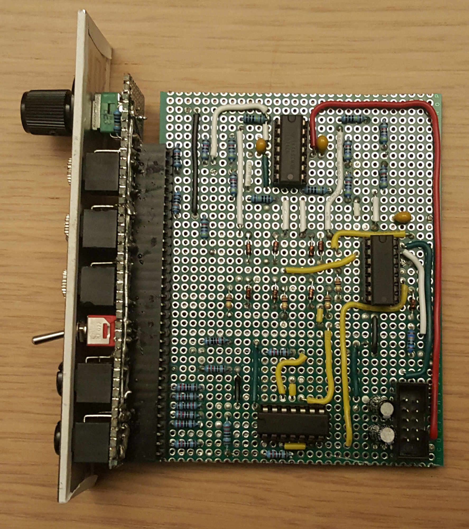
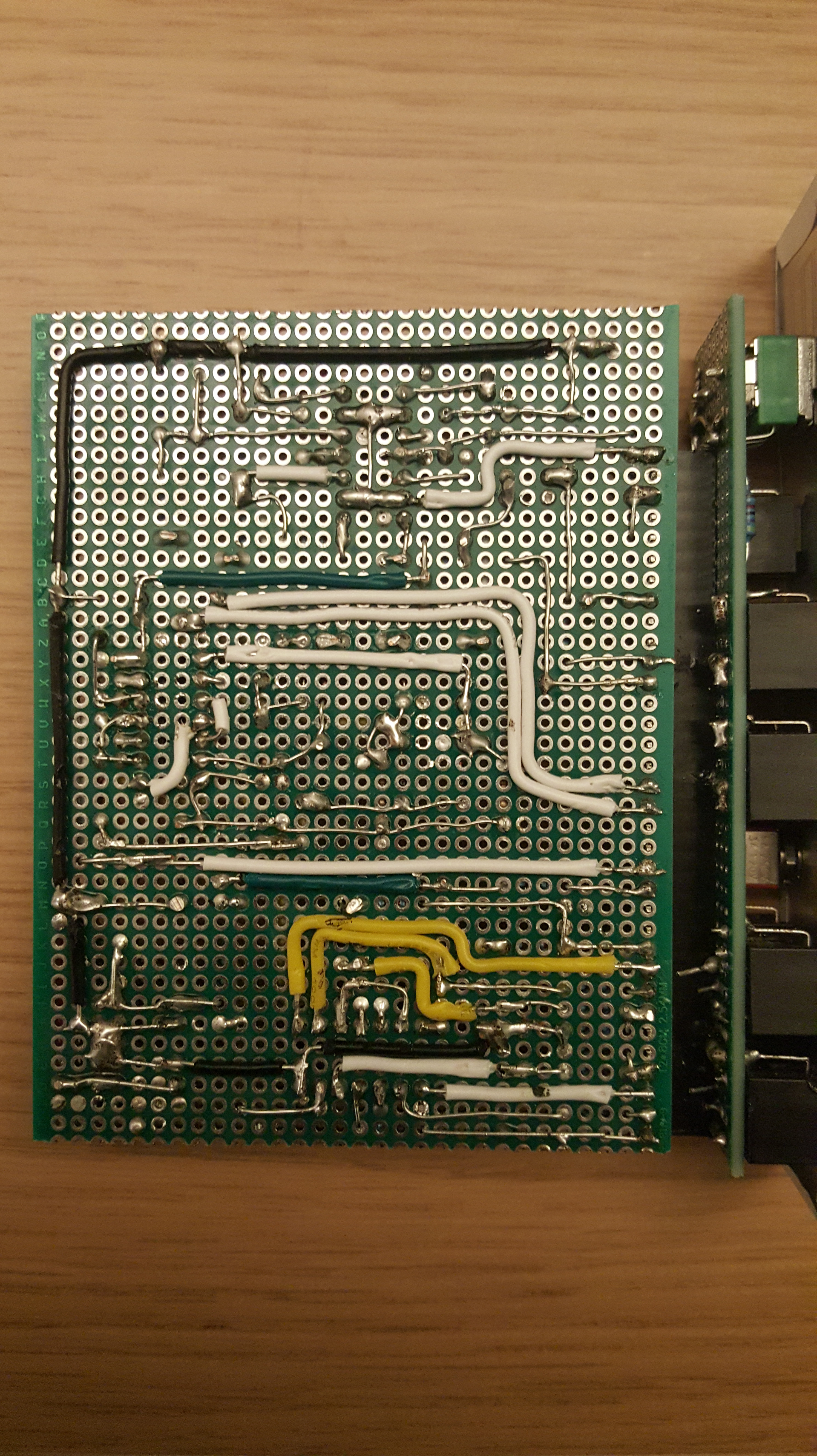
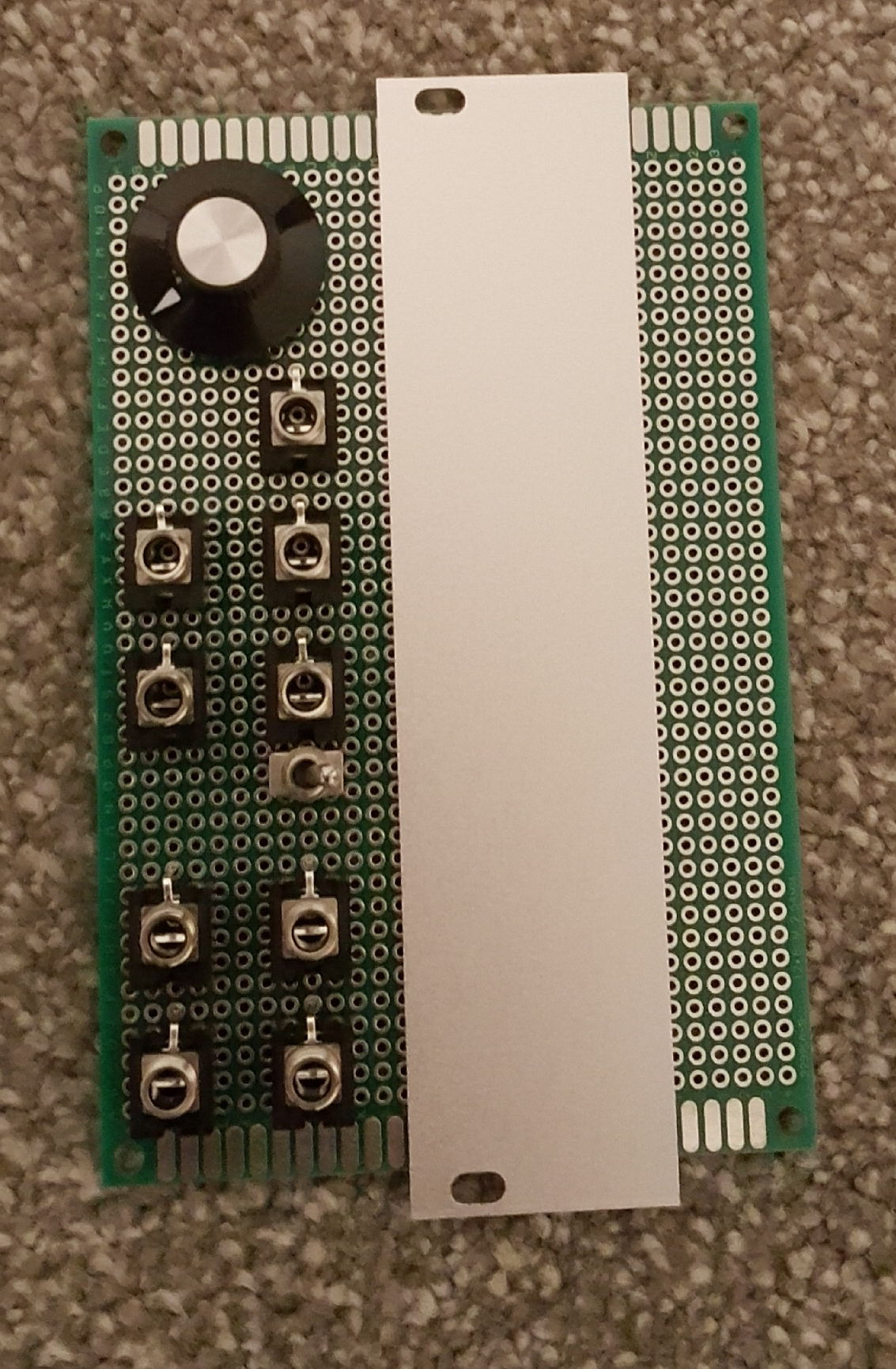
Mostly things get crowded around the three chips, which is understandable as each has four sections, taking inputs from a common direction and sending outputs in a common direction. Typical pin layouts do not facilitate this, so a bit of crossing-over is inevitable! But in KiCad this became quite a satisfying jigsaw puzzle; I can see how PCB design becomes a long refinement process.

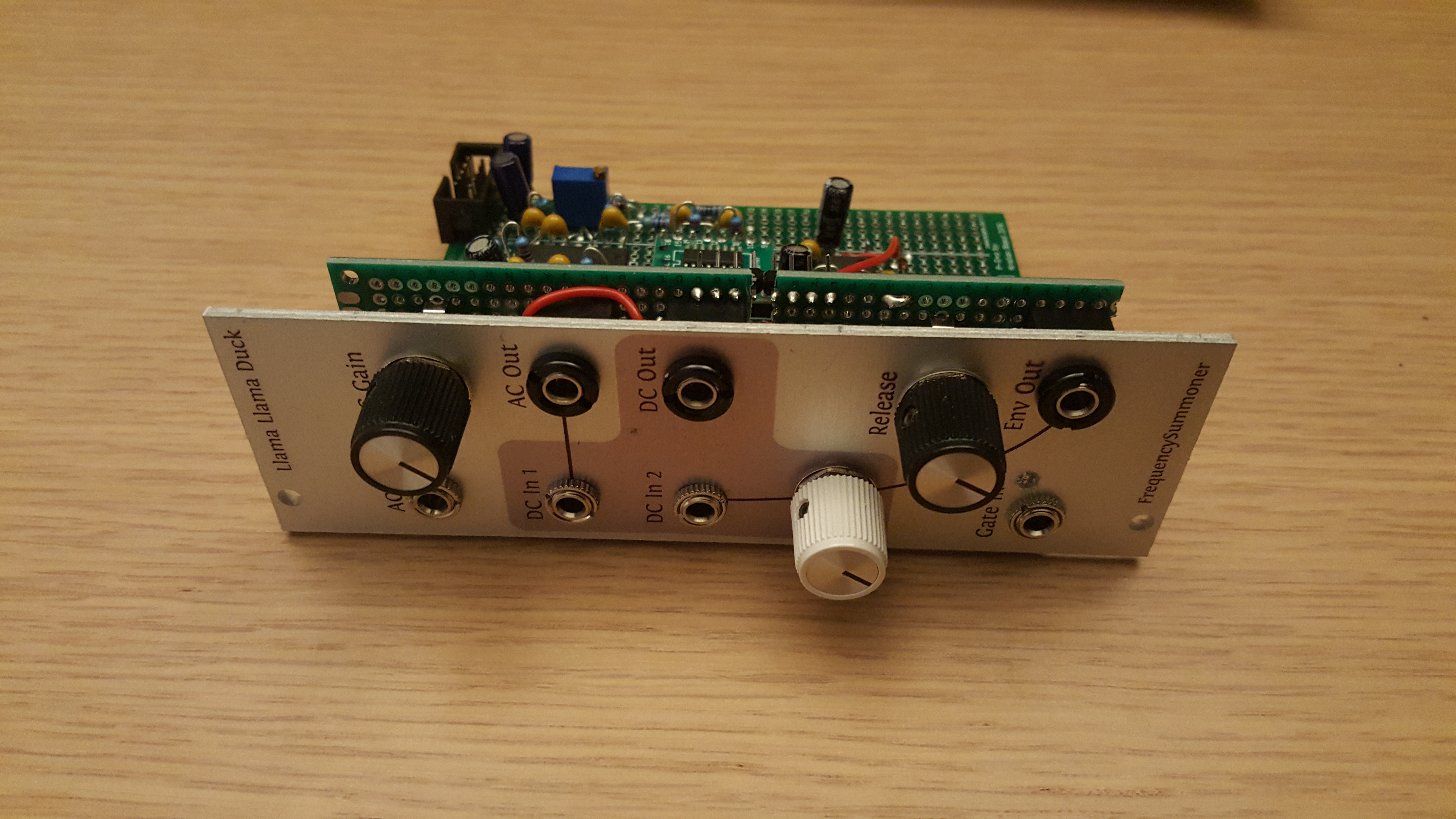
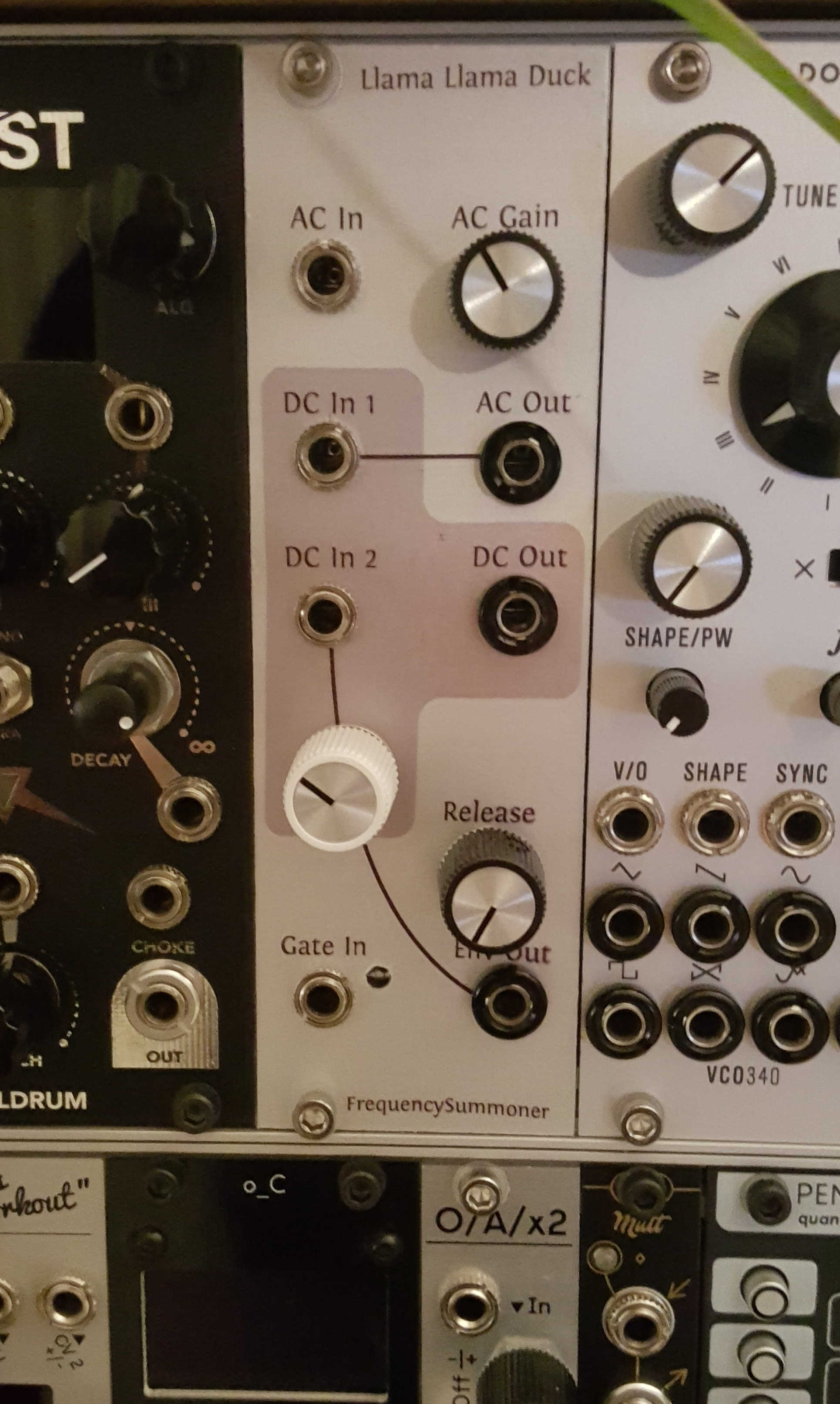
The front panel was worked out on paper and refined by plugging components into perfboard, before making a drilling template and transparency graphics in Inkscape. The end result looks pretty professional, but there is supposed to be a shaded rectangle grouping In 4 with the NOT switch and this is very faint. On Llama Llama Duck the shading was a touch dark. More experimentation needed!

Conclusions

I’m really happy with the form factor: 6hp with a big knob and LEDs tucked between two columns of jacks. It’s comfortable to use without much wasted space. It does the intended job as a modulation/logic processor but in practice is also a lot of fun at audio-rate, creating variable-width pulse outputs from sources other than oscillators. (Detuned groups of oscillators make good drones!)

Finished module making some drone music

Eurorack module design: LlamaLlamaDuck, a CD4049-based distortion envelope thing

I started designing my own modular synthesiser components. I wrote a few words here about how that fits into my life. This is my first original module design.

Well, I say original, but let’s give credit where it’s due: this is mostly based on stuff I’ve learned by looking at schematics from Nonlinearcircuits and Mutable Instruments, blog posts by Northern Lights Modular and hanging out on the Modwiggler forum. This particular design is also heavily influenced by some classic guitar pedals.

Llama Llama Duck assembled prototype module. The module is resting on its side and has an aluminium panel with labelled jacks and control knobs. Behind that are circuit boards with various components.

Overview

Here is a block diagram of the module. This makes it clear that there are essentially three independent functions, but default “normalled” connections link them together to provide a combined function. This structure is inspired by “Serge” design conventions, in which complementary units are brought together in a single panel, dividing up a regular grid layout of controls and jacks. However while Serge systems use “banana” jacks (which have the advantage of easily stacking to split one output to many inputs), Eurorack uses smaller and more complex 3.5mm jacks which include a “switching” feature to pass a default signal when disconnected.

Block diagram of module:

AC in runs through DC block and soft clipping to AC out.

"DC in 1" and "DC in 2" are summed, run through soft clipping to DC out.

Gate in runs through comparator to release envelope, then Env Out.

Normalled connections are shown with grey dashed lines: AC out is connected to DC in 1, the Release envelope is connected to DC in 2 and a +12V voltage is connected to the Gate In.

Distortion

So, what’s the deal with the AC/DC clipping stages? Well, I like the idea of the Tube Sound Fuzz, Red Llama and similar guitar distortion circuits, which abuse a CMOS logic chip to create a “tube-like” (soft and asymmetric) distorted gain stage. But guitar pedals have to make a few design compromises; although the input/output signal range is bipolar around 0V, they use a “single-sided” power supply between 0 and 9V (to support the use of convenient batteries). The processing needs to happen about some non-zero reference voltage, with a “bias” shift at the input and output. There’s an easy way of doing this: “AC-couple” the circuit with series capacitors. In the process we filter out the lowest frequencies; a non-issue for electric guitar. In a modular synthesizer this is sometimes a useful side-effect, getting a bit of headroom for unipolar input signals and avoiding excessively asymmetric clipping. The first section of Llama Llama Duck follows this scheme. The manual gain control can be used to dial things back into a kind of AC-coupled buffer, or push into pleasant distortion.

Circuit diagram 1
Section 1 schematic: an AC-coupled distortion section, similar to CD4049-based guitar pedals, is set between inverting opamp buffers which establish typical impedances for a Eurorack system.

Each inverter stage acts as an inverting amplifier when setup in this negative-feedback configuration. The principle is the same as an inverting opamp, making use of a linear region in the middle of the voltage range. There is heavy soft-clipping on one side of the transfer curve; to get something remotely symmetric we use two stages. The chip has six inverters on it, so we may as well use some more…

The joy of modular, for me, comes in the presence of generic processes that make sense for both control-voltage (CV) and audio signals. It should be possible to use distortion to reshape CV, and manipulate audio distortion by injecting interesting modulation sources. The above AC-coupling approach blocks DC and prevents such shenanigans. But the CD4049 can’t handle the full +/-12V Eurorack power supply; either it has to run “single-sided” or we need to regulate e.g. +/-6V rails within the module. I took the approach of dialling in bias voltages with a trimpot. Original experiments used two trimpots, but it turns out that one will do; as long as the output lines up properly (i.e. return 0V for 0V input) it doesn’t matter if the 4049 inputs are slightly off-centre.

Circuit diagram 2
Section 2 schematic: again CD4049-based distortion sits between op-amp buffers. This time there are no AC-coupling capacitors, and a trimpot sets the bias voltage for input and output.

A couple of other details are worth mentioning: a secondary input and clipping diode. Adding DC bias creates all sorts of nice fuzz effects, so an extra input is provided with a level potentiometer. (This works nicely with Section 3, as we shall see.) The diode is a precaution to prevent the U2C input node from being exposed to negative voltages if an unusually low input voltage is supplied. The inverting configuration keeps the node at ~6V but would need a lot of current in such a case. This shows up as a bit of hard-clipping in the output but isn’t really noticeable for sensible inputs.

The gain levels are fixed but fairly useful; a bit over +6dB of gain, and peak levels clipped to around +/-5.5V. This plays well with typical Eurorack oscillator signals which are 10V peak-to-peak. For more gain, consider pre-processing with section 1. For less gain, use the attenuating input.

Release envelope

Section 3 is a simple envelope generator with a fast attack stage, fixed sustain and variable release speed. I came up with it messing around on solderless breadboard but I doubt there’s anything unusual or clever going on: it’s just a comparator and slew limiter.

Circuit diagram 3
Section 3: Envelope generator with fast attack and variable release

An LED indicator is driven by the comparator rather than the output; not really clear if that was a good idea. The timing control uses a 1M linear pot in parallel with a 1M resistor to approximate a 500k logarithmic taper.

Why include a release envelope on a distortion unit, anyway? Well, it’s “normalled” to the DC In 2. If you send a clock to it, this will “fuzz” the audio running through that section’s other input by smashing the signal into one side of the clipping so hard it gets quieter. The result is something a bit like the classic dance music pumping / ducking effect. But weirder and noiser! That’s why this is the “duck” section. And when I realised that would mean the module could be named Llama Llama Duck, well…

Construction

After testing with solderless breadboards the circuit was built “freestyle” from the schematic on a Sourcery protoboard. The board was really nice to work with, having a neat power-bus system that allows IC power to be routed by soldering across a few pads. The control board was done with a few bits of regular perfboard, soldering wires and tracks to a header strip. In hindsight this would have gone more easily with a bit more planning; there was a lot of checking back-and-forth between the header strips, and mistakes were awkward to fix where leads crossed over.

Prototype module, side-view showing top of prototype board with components. One of the ICs is a small surface-mount component soldered to an adaptor board. A few jumper cables criss-cross around the board, but generally the layout is dense and tidy.
Prototype circuit on Sourcery Proto board.

The front panel was created as an inkjet waterslide on a drilled Doepfer blank panel. The drilling template and graphics were done with Inkscape. The knob/jack choices partly follow existing conventions in my modular system; I use chunky Bananuts to indicate outputs and knurled nuts for inputs. White knobs are attenuators, black knobs are offsets or direct controls. The waterslide colours ran slightly, turning grey into pink. I don’t really mind, but will try to refine that process a bit… I really like the on-grid section divisions of Serge-style panels and the consistent, informative design of Intellijel panels. I expect my approach will evolve, but for now the principles are: indicate independent sections; indicate normalisation; keep it playable. The ergonomics of knob/jack access are easily overlooked and many modules feel over-crowded.

Finished prototype installed in my modular synthesizer

Apologies if this post made absolutely no sense, it’s more of a DIY build log really. Hopefully there are more to come 😀

Analysis: Irongear Hot Slag Pickups

This article follows on from my previous post, discussing modifications to my Ibanez GRGR121EX, “Tess”. Recordings were made before and shortly after the new pickups were installed. The set of strings is the same (Rotosound pinks), as the new locking tuners made it fairly easy to detach and re-attach the strings as needed. However, the A-string broke and had to be replaced with a spare from a set of Ernie Ball Regular Slinky. This is a higher gauge so may have some influence on the recorded output of the new pickups in this range. However, I did not notice any dramatic change following the next re-stringing (more Roto-pinks).

Disclaimer

Many of the branded products referred to here are trademarked. I am not affiliated with any of the companies involved, and make direct reference to their products in the interest of accuracy and repeatability.

On online shopping

I spend countless hours trawling the internet looking at pictures of musical instruments and studio equipment. I purchase such items 2-3 times per year. This strikes me as a remarkably unproductive activity:

Useful information

  • Ability to fit into existing rigs and workflows
  • Reliability in practical scenarios
  • Quality of sound produced relative to other equipment
  • How it compares with similar items produced by different manufacturers
  • Ability to inspire new creative ideas
  • Ergonomics; comfort, ease of use

Information from manufacturers’ websites and online stores

  • How it fits into some common applications
  • Detailed specifications, from which other applications may be confirmed
  • Instruction manuals, from which ease of use and advanced capabilities may be inferred
  • Quality of sound through several arbitrary combinations of recording equipment
  • Where it fits into the range of products offered by the same manufacturer

Information from online reviews

  • Whether it survives being unwrapped and playing “smells like teen spirit” a few times
  • Whether it blows up spectacularly several years later
  • A blow-by-blow account of the argument/cosy agreement you will have with the store
  • How good it will look in a photo-shoot
  • Whether it sounds as good as your £10,000 rig (no)
  • Whether it sounds as good as your friend’s £10,000 rig (yes)

Even where the criteria are quite clear, it can be difficult to piece together the information you really need. Items such as guitars can be tried out in a store; but even then you are using an unfamiliar amplifier. For items such as recording interfaces demos are rarely available. Virtually all of my MIDI equipment has been purchased largely based on their user manuals; the free PDF user manual is a godsend for  a synth geek trying to construct a flexible clock-synchronisable program-changeable remotely-controllable live rig. Whether it will sound any good is completely unpredictable.

Pickups

A guitar pickup is not a terribly complicated device. However, there are many conflicting approaches to making the best pickups. Hand wound or machine wound? Scatter winding? More powerful magnets for high output with less noise? Weaker magnets for less string pull? I will not go into a detailed discussion of the different types of pickup here, as it has been done elsewhere many times, but it is difficult to avoid a little cynicism. Why do some pickups cost so much more than others, when the construction should be identical?

I decided on the Irongear Hot Slags for my project (see previous post): the reviews were good from a range of websites, and they seemed to offer a “modern” sound with some character. I was particularly intrigued by a helpful graph, promising a hot, mids-heavy sound. My stock Ibanez pickups have the styling of EMGs, but this says nothing about their sound. It is unlikely that they give the “flat” sound that EMG’s active range are famous for.

Method

All recording was done into Logic Pro 8 at 24 bit 44.1kHz,  using the direct guitar input of an Edirol UA-4FX interface. The Match EQ is an inbuilt effect used for calibration. I used the calibration mode to produce a graphic representation of the material it is exposed to. For each pickup configuration I played a simplified version of the guitar part for a song called “No More Days”. This is a song I originally wrote for a band at University, and has subsequently been adopted and adapted by one of my other bands, Broken Console. The studio recording is free to download.

Old vs New

Ibanez GRGR121EX Factory Pickups: Bridge (left) & Neck (right)

Examining the curves generated by the factory pickups: the bridge pickup gives a surprisingly flat response, while the neck pickup has a pronounced hump in the bass end. The small peaks and troughs may be disregarded as a consequence of the source material, which is all in one key and heavily favours some notes (and hence frequencies). The neck pickup may be expected to show a strong bass response as the string movement is greater at the neck pickup for low notes. High harmonics, on the other hand, dissipate quickly and are usually more prominent in the bridge position.

Irongear Hot Slag pickups: Bridge (left) & Neck (right)

Examining the frequency response of the Hot Slags, the bridge response is surprising; it appears almost identical to that of the factory pickup. The overall level is around 2 db higher, which is an audible difference but not huge. The neck pickup displays a similar increase in output, but the bass frequencies are even more dominant.

It is not practical to examine all of the coil-tapping and phase-flipping possibilities of “Tess” following modification. However, there is one combination I have been using a great deal, which merits inclusion. The pickup selector is in the middle position, the bridge pickup is set as a standard humbucker, the neck is coil-tapped and out of phase. This gives a very distinctive “hollow” sound.

Tess' control panel. Just as bewildering on-stage as it is in this terrible diagram.

Irongear Hot Slags: Bridge in parallel with neck pickup coil-cut and out of phase

It can be seen from the figure that the output drops substantially due to the phase cancellation, and a “gap” appears in the low-mid frequencies around 300 Hz. This gives a “scooped” sound which interacts well with high-gain amplifier settings.

Conclusions

On paper, the frequency response of the new pickups is very similar to the frequency response of the factory pickups. The “character” of the guitar has not significantly changed. However, the new options open up a range of new sounds, and a higher output is available.

This graphical examination has not addressed the subjective measure of “clarity”. It is claimed that high-quality pickups make it easier to distinguish the individual notes of chords, even with distortion. The source material is made available in compressed form below. I you would like a copy of the recordings in a lossless format, please get in touch.

Stock pickups: Bridge

Stock pickups: Neck

Irongear Hot Slag: Bridge

Irongear Hot Slag: Neck

Irongear Hot Slag: Bridge + Coil-cut neck (out of phase)

Potential developments

While the Match EQ is very convenient, I would prefer to use something a little more rigorous, and capable of returning a numerical output. It’s possible that my dabblings in programming will arm me to write something appropriate. If you know of a suitable existing tool, preferably FOSS, please let me know!

Playing back a piece is difficult to do consistently, and far from ideal. One option for future tests would be to try to directly stimulate the pickup with an e-bow or a headphone earpiece playing pink noise. A more appealing option is to construct a consistent “guitar-plucking machine”, possibly using LEGO. Any designs or suggestions are welcome.

Further experimentation is needed to confirm the claim that some pickups are “clearer” and “more dynamic” than others.

Upgrading Tess

As a post-exam treat, I set about upgrading one of my guitars. My inner artist wanted something inspiring with more options. My inner perfectionist wanted higher quality and better technology. My inner poseur wanted something that looked “custom” but tasteful.

The guitar

“Tess” is an Ibanez GRGR121EX, acquired from a guitar shop in Abingdon. It’s available for about £150 online, but the shop price was £190. Given how variable quality is in this price bracket, this may have been justified for the privilege of checking it was not, in fact, a lemon. Then again, I was planning to replace most of the parts eventually anyway…

Ibanez GRGR121EX
Complete with EMG-style stock pickups and all-black hardware. The strap buttons have already been replaced with a locking system.

Machine heads

Tuning stability was not great on this guitar. In fairness, my reference point is my other electric guitar, which is made out of resin and so not susceptible to temperature or moisture. Nonetheless, I felt there was definitely room for improvement on the tuning system. I’ve been interested in locking tuners for a while, and also fancied a change from all-black hardware to a mixture of black and chrome. The guitar has a reverse headstock, however, which greatly limits the choice of affordable locking tuners. This is one of the less obvious drawbacks to a reverse headstock; you need left-handed hardware! (Or, if you prefer, this is a point in favour of reverse-headstock left-handed guitars.) In the end I got them from axetec, along with the other parts used in this project.

Locking tuners are beautifully simple in use. Simply pull the string through the hole, tighten up, and cut off the excess. Less winding means less slipping and stretching, as well as saving you a minute or so every time you change strings.

If you loosen the thumbwheel enough, it is possible to see the gearing in this system.

As the thumb-wheel is tightened, a rod pinches the string in the hole to prevent slipping. The excess can be cut off close to the hole.

Machine heads are typically divided into “sealed” and “open” designs; open tuners have an exposed mechanism and are easy to oil and maintain. They are common on acoustic guitars and bass guitars. Sealed tuners keep the mechanism tucked away from the elements, and in theory don’t need any maintenance. They are used on the vast majority of electric guitars, and many electric bass guitars as well as some acoustics. These locking tuners are an interesting case; they are generally sealed, but the mechanism is exposed when they are loosened for restringing. Best of both worlds? Worst of both worlds? Time will tell…

The factory tuners don’t have a visible screwhole; in fact they are built with two studs on the underside which sit into corresponding holes in the guitar headstock. This is quite an elegant design, and also meant that while I had to drill new holes, the old holes would at least be hidden by the new machine heads.

The factory tuners are relatively compact, and interface with two small holes to prevent twisting. These are completely covered by third-party tuners.

Drilling the holes for the new screws was a little intimidating, as the screws extended into about ¾ of the total head thickness. I used a hand drill with a 2mm bit. Thankfully the actual holes and washers for the tuners were all a standard size, so there was no difficulty threading the new tuners through.

Control Knobs

The original knobs are made of black plastic and feel cheap. I could also feel some drag when turning them, and procured new potentiometers, assuming that these were faulty. However, while fitting the new, shiny and reassuringly heavy telecaster-style knobs, I discovered the real problem; if the knobs float just above the body, they move easily. If they are set at an angle, or too close to the surface, they drag. So, if you’re finding odd resistance from your control knobs, get a screwdriver out and try mounting them 1mm higher. It may save you a few quid on new electronics you don’t need!

Pickups

I must confess to some skepticism regarding pickups. It is difficult to understand why there is such a variety in the pricing of such a well-established and simple product. There really can’t be that much difference between the magnets and copper wire used in a £5 ebay pickup or Seymour Duncan’s finest, can there? Obviously the design is significant, and it is uncontroversial that pickup choice is one of the most significant factors determining a guitar’s tone, along with amplifier and playing technique. Still, I fancied something with a modern meaty sound, and some flexibility. I settled on a pair of Irongear Hot Slags with chrome covers. Definitely moving away a little from standard Ibanez territory here.

The Irongear Hot Slag is a high-output humbucker with a mids-heavy sound. These were nicely presented and ready for coil tapping and other trickery…

The factory pickups these are replacing are in a matt black casing evocative of EMG pickups, and strongly implying that they are active. In fact, these are simple passive pickups, set in a black resin which would have made rewiring the coils difficult.

The factory pickups are simple passive humbuckers, set in resin to add a little durability at the expense of tinkering

Unfortunately, they are also slightly smaller than the Irongears, and a buildup of resin around the base of the guitar neck resisted the insertion of a shiny replacement. After a little filing there was a sickening “CRACK” and small piece of resin came away, exposing more of the neck pocket. Once I’d started breathing again, I remembered that the neck is in fact held in place by four massive bolts, not a layer of resin, and that this was probably nothing to worry about. This created the needed space, and the guitar’s chrome content was increased accordingly.

*Just* too small

As is common for “upgrade” pickups, the Hot Slags provide separate access to each end of wire for each coil, as well as the cover grounding. This opened the way for some ambitious wiring schemes. I based the wiring on this design from the very helpful guitarelectronics.com, with an additional phase flip switch between the neck pickup coil selector and the main 3-way pickup selector switch. One note for those who wish to try this for themselves; I also had to swap the left and right sides of the coil-selector lugs to match the wiring on my own 3-way switch. Also, not all 3-way switches will work. 1728.com offers a fairly clear explanation of different kinds of switches and their use in guitar wiring.

Fiddly stuff this wiring. Horribly out of practice at soldering.

The most hair-raising part of the whole process was in fact drilling holes for the new switches. The guitar finish is fairly brittle, and drilling risked cracking and splintering the surrounding finish. For each new switch, I drilled a 3mm pilot hole from the inside of the cavity (to make sure there was room for the switch!), then, working from the face, removed more material with 4mm and 5mm drill bits. This would lead to 1-2mm of damage to the surrounding finish (if I was careful!), and from there I used a file to enlarge the hole to accept the switch. Unfortunately the switches are barely long enough to reach through the body; I intend to rectify this by removing a few mm of material from the inside with a pillar drill and large bit when I next have access to them. Still, the final result is neat and distinctive!

The top-most switch controls the phase of the neck pickup. The pair of switches above the tone knob switch each pickup between series, parallel and single-coil configurations.

£150 guitar + £100 new hardware > £250 guitar

Coming soon…

I’d like to analyse the actual differences this has made. It’s very difficult to choose pickups online, or in a shop for that matter, because of the lack of a baseline comparison. Soundclips are nice, but they tell you more about who has the nicest amplifier than who has the best pickups.

If you have any questions about this project, feel free to leave them as comments and I’ll try to get back to you soon!